SO... it's been a while, yes?
I would usually preface this with an apology for the lack of posts in the last 30 some odd days but that's not what you're here to see. You want the good stuff.
With that, I give you Miniwaves of Majorpain: One Man's Odyssey Into Making The Unfit-able... Fit.
We start with two PlanB Miniwave faceplate euro kits. They come with a handy, dandy warning letting us gentle folk know that the kits will not allow for the Miniwaves to fit into the confines of the Doepfer portable or monster case systems naturally due to the minwaves inherent depth while only letting them fit between bus board connectors in the more standard G6 cases.
Bullocks, rubbish, nonsense, you don't tell me what to do.
So with those words in mind, I set out to do just that.
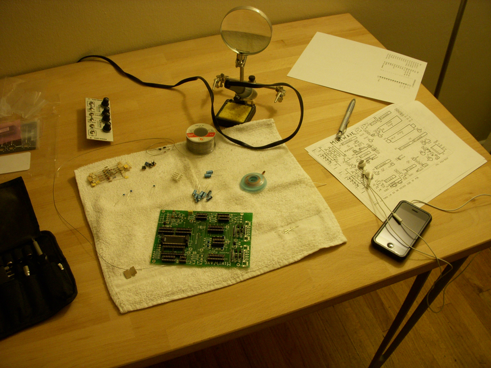
I'd like to point out that this was the first module kit I've ever put together from start to finish. My only other experience being with soldering of the wiring of jacks to the PCB of a Blacet Time Machine about four or five years ago that a dear friend of mine built 98% prior to my "work." In other words my skills with the iron were less than satisfactory. But that didn't stop me, for now I had time on my side, patience as my virtue & a metric shit-ton of ignorant bravado.
I laid out a course of action to finish the task at hand without feeling overwhelmed. I spaced out the work in 90 minute chunks over the span of five days, those being Monday through Friday. Although I'm sorry to say Wednesday was thrown out the window not do to my lack of caring, but more for my lack of consciousness. Thursday was the utmost frustrating & feverishly conducive towards me hitting fragile things with heavy, blunt objects. In aforementioned "fourth day" It was time for the point to point soldering of all the faceplate components via wires to the PCB. Thats 43 wires, 86 patch points. Now it wasn't so bad until it came down to the LED & Potentiometer prongs. I've not been as agitated or so easily angled towards rage in any point in my life, I'm pretty sure.
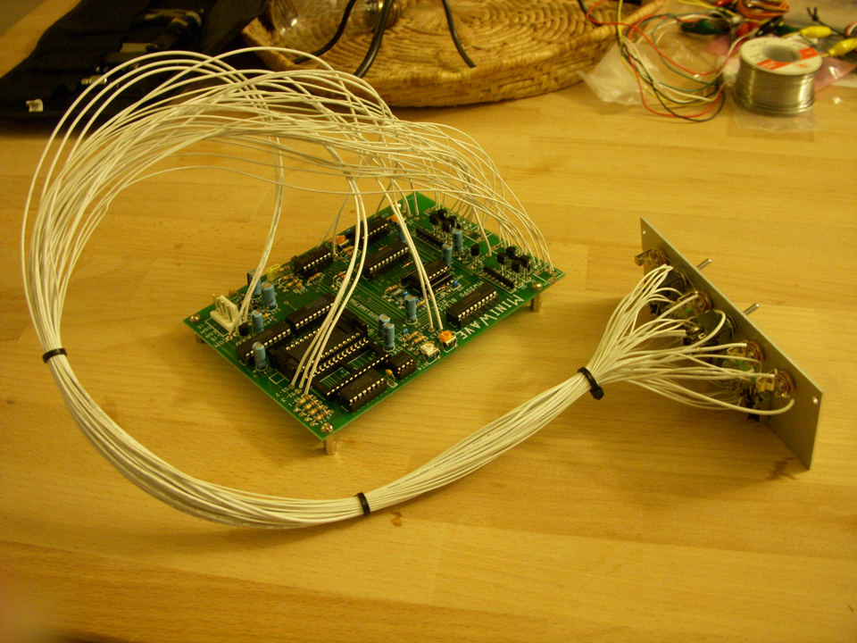
(As a side note, the LEDs are designed to be held in place by only the holes holding them to the PCB. They are purposely angled so they stay seated into the faceplate in that arrangement. Well... not so with how I needed to attach them. Instead I had to buy a hot glue gun and make like I was practicing for my money-shot moment. But I have to admit, it held them in place perfectly.)
And now its done, right?
Not without the proverbial hiccup mind you. (please, READ the instructions thoroughly. Don't skip over the jack solder assignment just because you're looking at the picture and holding your PlanB faceplate in your hand. Nice little tip, the jacks aren't in the same order top to bottom as on the Blacet faceplate. This was entirely my fault and not the fault of anyone else.) I'd like to give a thanks to Gur from Tiptop Audio for having the kindness in his heart to read the schematic for me (did I mention how bad I suck?) and showing my error.
Then there was the problem of how to get the PCB into the case. I knew I had to rest it @ the bottom of the case and while doing so I wanted to install stand offs to lift it from the floor of the unit. FAIL. You can't get the PCB in that position with stand offs installed except by maybe removing the bus board first. (No thank you.) So I chose to insulate any metal in that section of the case that could possibly touch the pcb via electrical tape for now until I devise a proper, long term solution.
Lastly, while installing the PCB you must disconnect the power adapter PlanB provides due again to it not being able to fit in its location otherwise. After it's secure your all done.
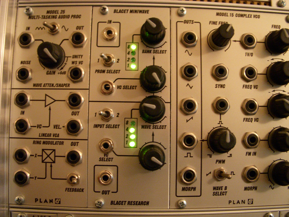
So here it is, in all its defiant glory. A Blacet Miniwave humming quite happily inside a Doepfer Monster Case.
Here is a link to all the pictures I took over those 5 days.
Now forge on you rebels and install one (or more) of your own!
I know I will be.