Saturday, December 20, 2008

Livewire Vulcan Modulator DIY Expander

Someone once told me, in reference to their skills with a soldering iron: "..I know just enough to be dangerous.."

I liked that, but in my case its far more appropriate to say: "..I know when I see blue smoke I've done a bad, bad thing.."

Luckily in this case, it all worked out just fine. (for now)


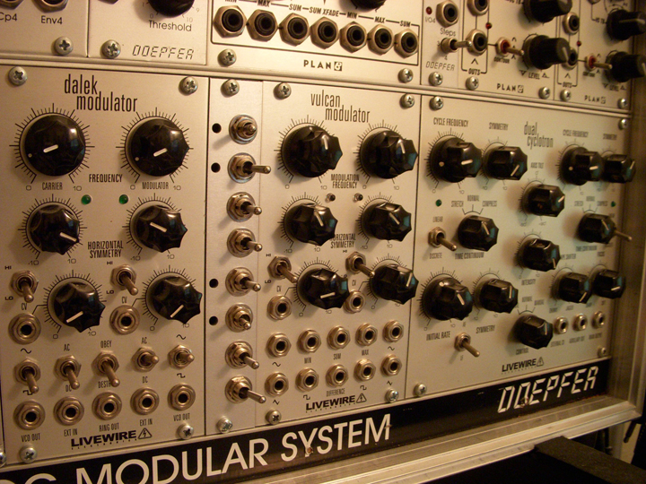
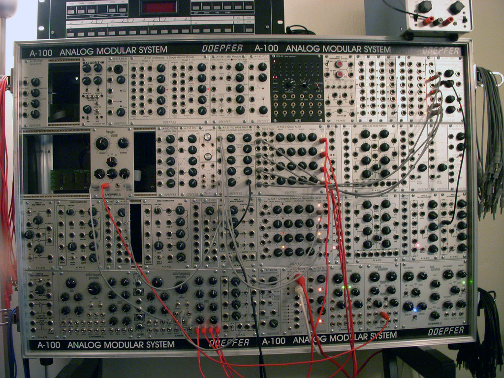
Having owned a Vulcan Modulator since they were first up for grabs @ Analogue Haven back in 2006 I've always appreciated it as a great source for discombobulated modulations and quirky effects. Even using it as two very effective LFOs when the CV inputs are not in use and the attenuators are at zero.


Its greatest feature is of course the Max, Min, Sum & Difference outputs that allow for an even greater palette of choice when it comes to a modulation source. But what I didn't like was having to power down the case, unscrew the module, move the jumpers, place the module back in, power on the case again, let the modules warm back up and THEN see what the combination sounded like. (I never had a long enough power cable to do this procedure  without powering down the case)


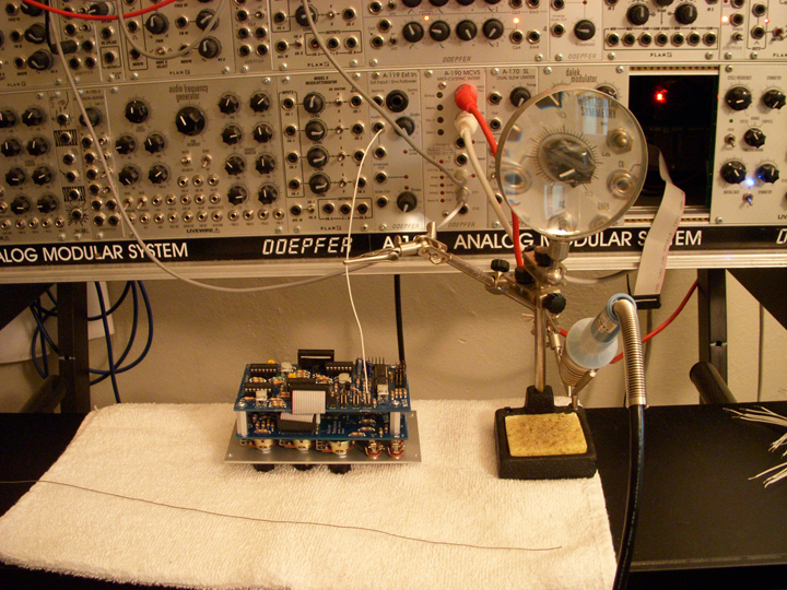
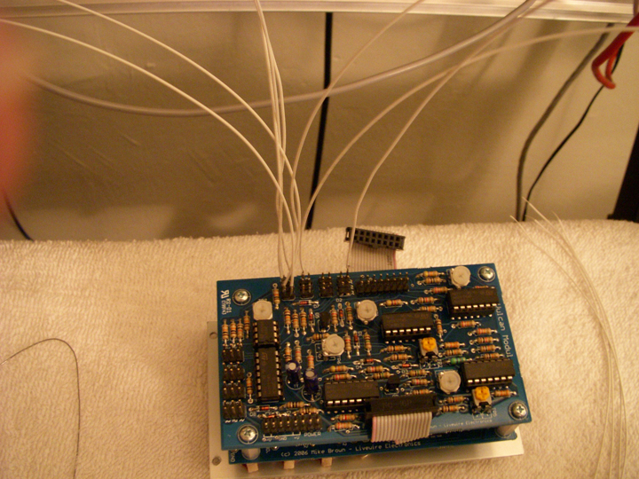
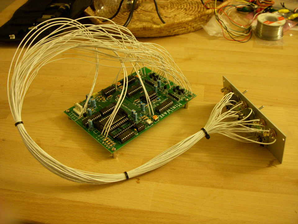
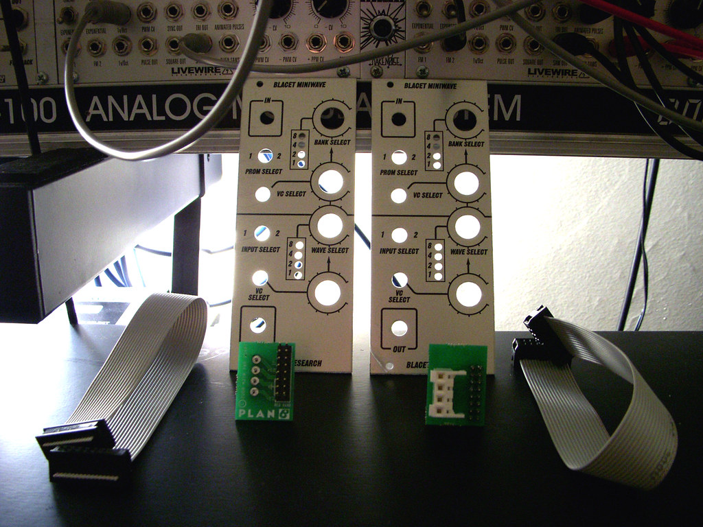
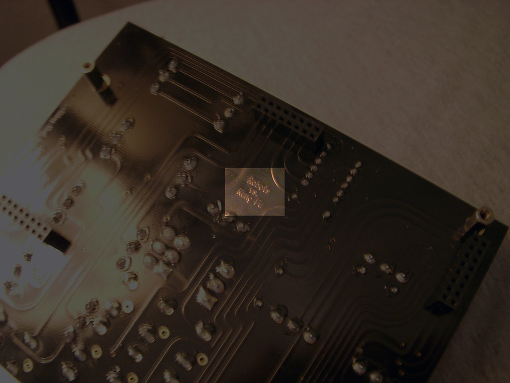
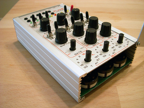
So I took it upon myself to make a small expansion unit to sit beside the Vulcan Modulator that would allow me to switch the waveform mixes around in real time with just the simple option to select either Sine, Triangle or Square waveforms. I remember seeing expanders on either side of one of the Vulcan's Mike Brown had @ NAMM '07. It took some figuring out as to what form factor, what components, etc. to make it possible but it was by no means a very hard task to determine how to do it. The problem laid in connecting all those individual jumper posts without accidently dropping a touch of solder across two making a permanent connection. (had I not known I did it)


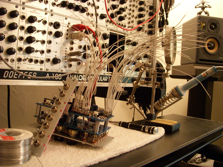
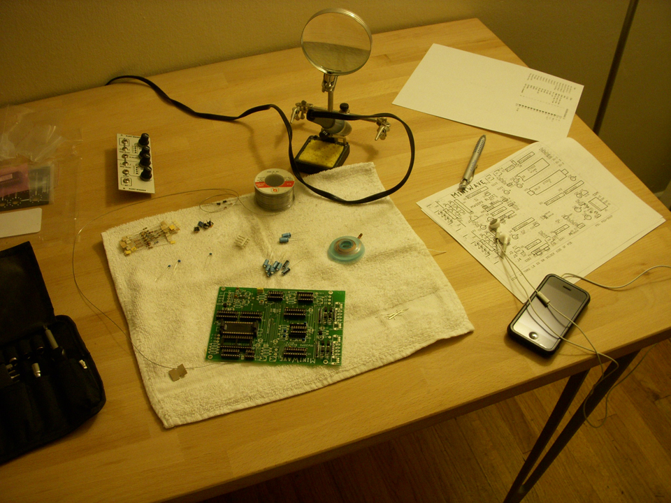
As with the Miniwave Euro Kit I spread the task out over a few days so I would lessen my chances of such a screw up. As luck would have it, when the module was placed back in the case and powered on (on a bus board all by its loansome at first, for safety's sake) it lit up and worked like a charm. 


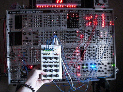
I can now switch the waveforms in real time and have a little more hands on control with the complexity of the modulations to suit whatever mood I find the patch to be going in. Here's a short demo of it working. (warning: TERRIBLE video quality)


I even planned to do a run of simple but up-to-par 4hp faceplates to create kits for others to do that same. But that can not be &  the reasons for it are understandable.  Hopefully soon Livewire will bring out a much better and feature heavy expansion module in the future, I look forward to seeing such a thing.

Monday, December 15, 2008

I only like bubbles in my champagne...

...but for this particular module, i'll make an exception.

So who is this manufacturer anyway? 

BubbleSound has an interesting philosphy in that they use some NOS components (in the case of the module on the block today, the SeM20 V|S|F; we are experiencing the sound of NOS transistors and opamps) in their product. Boutique guitar pedal manufacturers (fuzz pedals in particular) have a penchant for using NOS germanium or silicon transistors to help obtain that vintage feel. So why not the same concept for modules?

I for one have never personally been too attached to the notion of needing a certain piece of gear to capture the sound i'm looking for. Within reason, any able-minded synthesis should have the capacity to create workable sound from any synth with full parameter control that they might have in front of them. 


With that being said I was impressed with the sound quality of the SeM20. Its character was a softer, more rounded color scheme that some of the more harsh and gnarly filters that seem to frequent the eurorack format world. Yet it broke up with a nice grit in the final stages of the input attenuation and frequency knobs rotation.

Each filter modes output sounded good to my ears for its purpose. When combined with the AFG square wave output, (a module which uses 70's era tracing and component techniques) I was impressed with the outcome. It sounded vintage-eque to my ears at least.


The most unique feature from the other eurorack filters is its Notch Balance knob. Giving you, the user; the ability to shift the notch balance closer to either the LP or HP sides of the spectrum. giving a nice phasing sound you hear near the end of the clip above. I really wish it was voltage controllable though. :(

Now that I've said my positives i'll hash out the few, (but still unavoidable) negatives which may or may not concern most users.

1) Their website states that the filter will self oscillate. Mine came unable to achieve this. It might be as simple as a trim pot adjustment but its still worth noting.

2) Something that doesn't impede its sound in the least; its layout, knobs and faceplate font. This little darling is not winning any beauty pageants, thats for sure.  I would have much rather had all the filter outputs across the bottom of the module in a nice even row while all the knobs would be shifted into two, symmetrical columns. That would leave plenty of room for that really nifty CV input for the Notch Balance. (hint, hint)

So there you have it. In the end I find this filter to be a very worthwhile purchase that can add an older (ie: more distinguished) sheen to your fairly modern filter arsenal.


Wednesday, November 5, 2008

You had me at "HELO"


Tiptop Audio's Z3000 to be exact.

Having had the opportunity to utilize not just one, but for a short time, up to four of these newly minted oscillators in my own system; I have to say the Z3000's utilitarian & highly convenient frequency counter was, as with most who first look upon the module, the initial draw and drool factor. Let alone its ability to also show the note & octave state the module is currently outputing with the bonus of an external in to utilize the frequency counter with all your existing oscillators to boot! 


The unit is completely analogue aside from the frequency counter. It is rich and warm with one of the best sine waves I've had the opportunity to use. It's by no means pure & that's most likely the reason for it sounding so good to my own (& the others) ears who've been fortunate enough to test and play with these lovely modules ahead of time.

The other wave forms are very good & for me the pulse especially, with its full sweep pot that dosen't dead end or drop off near the limits of the pot's radius. Would I have liked a dedicated 50/50 duty cycle square wave output too? Of course, but at this price point to feature ratio I am not about to complain!

A nice feature that helps alleviate the need for a multiple is the CV out thru-put on the unit. You can cascade multiple Z3000's or send that CV to another oscillator without the need for a middle man to make the connection. (hush you banana jack users, I know already what your going to say) There is even a jumper on the PCB to allow you to connect it to the Doepfer CV bus, all the while still having the 1v/oct input active for use.

You'll notice another feature that is unique to
 this particular oscillator & that is its HSM input. Hard Sync Modulation allows you to input not just the saw or square waves that have a hard edge but also triangle and sine waves with varying effect from each waveform. You can even input whole tracks and external audio signals from you DAW or other source to distort and rectify the waveform according to the incoming signal. Also worth noting is the fact you can use both inputs at the same time, having frequencies fight it out in a duel to the divisible-death if you will. Nifty stuff. :) 

Below is a simple example of that very thing. Only four modules and three patchcords are in use here. Two Plan B Model-15 oscillators as the sync sources. The sine wave output from the Z3000 is going directly into a VCA set wide open. One M-15 is used for its pulse out going into the Sync input & the other M-15 has its sine out going into the HSM input. The frequencies of the two M-15's are set as the Z3000's frequency is slowly swept up and back down again. Then random frequency changes are applied manually to the individual M-15s as well as the HSM input source being changed from sine to triangle to sawtooth.


The FM is also lovely. It's not as "out there" as the Plan B Model-15 can get but it's a new and very choice color to add to an existing color scheme. If I had the brain power left tonight i'd upload an audio demo but that will have to wait until later, unfortunately.

With that said I can definitely say I would not want to be without this guy from now on. Especially with it's handy frequency counter allowing me to subdivide & multiply frequencies with greater ease to create harmonic overtones as well as adding or subtracting by a set integer for inharmonic overtones both of which come in great handy not only for FM but for rhythmic beating of the tuning when mixed together, etc. etc.

Oh, and this last image is for Surachai: Super Devil Brutal Metal Frequency


Sunday, October 5, 2008

Miniwave, Majorpain


SO... it's been a while, yes?

I would usually preface this with an apology for the lack of posts in the last 30 some odd days but that's not what you're here to see. You want the good stuff.

With that, I give you Miniwaves of Majorpain: One Man's Odyssey Into Making The Unfit-able... Fit.

We start with two PlanB Miniwave faceplate euro kits. They come with a handy, dandy warning letting us gentle folk know that the kits will not allow for the Miniwaves to fit into the confines of the Doepfer portable or monster case systems naturally due to the minwaves inherent depth while only letting them fit between bus board connectors in the more standard G6 cases.

Bullocks, rubbish, nonsense, you don't tell me what to do.

So with those words in mind, I set out to do just that.

I'd like to point out that this was the first module kit I've ever put together from start to finish. My only other experience being with soldering of the wiring of jacks to the PCB of a Blacet Time Machine about four or five years ago that a dear friend of mine built 98% prior to my "work." In other words my skills with the iron were less than satisfactory. But that didn't stop me, for now I had time on my side, patience as my virtue & a metric shit-ton of ignorant bravado.

I laid out a course of action to finish the task at hand without feeling overwhelmed. I spaced out the work in 90 minute chunks over the span of five days, those being Monday through Friday. Although I'm sorry to say Wednesday was thrown out the window not do to my lack of caring, but more for my lack of consciousness. Thursday was the utmost frustrating & feverishly conducive towards me hitting fragile things with heavy, blunt objects. In aforementioned "fourth day" It was time for the point to point soldering of all the faceplate components via wires to the PCB. Thats 43 wires, 86 patch points. Now it wasn't so bad until it came down to the LED & Potentiometer prongs. I've not been as agitated or so easily angled towards rage in any point in my life, I'm pretty sure.


(As a side note, the LEDs are designed to be held in place by only the holes holding them to the PCB. They are purposely angled so they stay seated into the faceplate in that arrangement. Well... not so with how I needed to attach them. Instead I had to buy a hot glue gun and make like I was practicing for my money-shot moment. But I have to admit, it held them in place perfectly.)

And now its done, right?

Not without the proverbial hiccup mind you. (please, READ the instructions thoroughly. Don't skip over the jack solder assignment just because you're looking at the picture and holding your PlanB faceplate in your hand. Nice little tip, the jacks aren't in the same order top to bottom as on the Blacet faceplate. This was entirely my fault and not the fault of anyone else.) I'd like to give a thanks to Gur from Tiptop Audio for having the kindness in his heart to read the schematic for me (did I mention how bad I suck?) and showing my error.

Then there was the problem of how to get the PCB into the case. I knew I had to rest it @ the bottom of the case and while doing so I wanted to install stand offs to lift it from the floor of the unit. FAIL. You can't get the PCB in that position with stand offs installed except by maybe removing the bus board first. (No thank you.) So I chose to insulate any metal in that section of the case that could possibly touch the pcb via electrical tape for now until I devise a proper, long term solution.

Lastly, while installing the PCB you must disconnect the power adapter PlanB provides due again to it not being able to fit in its location otherwise. After it's secure your all done.


So here it is, in all its defiant glory. A Blacet Miniwave humming quite happily inside a Doepfer Monster Case.

Here is a link to all the pictures I took over those 5 days.

Now forge on you rebels and install one (or more) of your own!

I know I will be.


Wednesday, September 3, 2008

VC Bit Modifier Expansion Port Update.

I Asked Shawn @  Analogue Haven if there was any information on the possible future expansion for the A-189-1 . 

My friends, the future looks interesting.

Below, in Dieters own words, he explains what could become reality if there is enough interest:

we think about an expansion module for the A-189-1 that would allow  some
additional features, e.g.:

- digital VCA at the audio input (one would not need a separate VCA  at the
audio input for certain bit modifier effects, if you already worked  with the
A-189-1 you should try a VCA controlled by an ADSR at the audio  input, then
you know what I mean !). For this an additional CV input is required
(available at the expansion module)
- voltage control of the mode (e.g. if the rotary switch is in  position 16
the mode can be voltage controlled by an additional CV input  available at
the expansion module)
- digital ring modulator (similar to A-114 but digital with VC  sampling
rate)

So far there is no release date for the A-189-1 expansion module.  For now
the A-189-1 users seem to be happy with the available features. But we
wanted to be open for possible additional features. Of course the software
(i.e. the microcontroller) has to be changed too.

So there you have it. I just hope the future owners of this module with be as selfishly unsatisfied as I am & give their vote toward its creation until the expansion module because a reality. ;)

Tuesday, September 2, 2008

I want to crush you to bits...

And so I shall, in 16 varieties not less.

Well, technically 11 varieties with a few short delays loped in for good measure.... but who's counting?

I'm not qualified to explain this modules settings in a manner befitting its design so I'll let the moving picture below do the talking for the most part. For a proper explination of each setting I recommend Doepfers own A-189-1 page. 

I used a simple sine wave for demonstration purposes so you could actually see what the varied settlings were actually doing to the waveform itself on the scope. Some settings don't sound all that different from the previous or might not sound like much at all. This is mainly due to the source with which i'm feeding it. A static wave with no movement or harmonic content to speak of is not what some of these settings would prefer. Prior to recording this demo I was feeding it Princes' Lets Go Crazy. Trust in the fact that there is more to this unit that what is shown. 


While I was installing the unit I notice there was a nifty little pin connection point that was labeled "Expansion" on the PCB. I'm very curious as to what it is exactly that Dieter has in store for it.


Over all I'm very satisfied with this module. It does quite a bit (totally unintentional pun that i'm too sappy to now remove) for such a small footprint. But I will say this; it is not a Malgorithm replacment. Its hard to explain but with them side by side they are two similar means with slightly different ends. For those of you thinking of letting go of the Malgorithm just because this is now available please keep in mind it is a complimenting addition, not a substitution.


Saturday, August 30, 2008

Plan B Blacet Miniwave Euro Kits


Just got back from Noisebug with the two kits I ordered.

They come with the bare faceplate, the power adapter & a power cable.

The units are 10hp & even have the protective plastic still attached for those (like myself) who won't be installing them right away. Its gonna be a little more work to squeeze them into the monster case than just replacing the faceplate.

Fun.


Tuesday, August 26, 2008

Gnomes are not Elves


Took in two Plan B M-37 ELF LFO's this weekend.

I have to admit I was a tad skeptical during the procurement. In swapping out my trusty Doepfer A-145's "what will I do without my sine and inverted saw outputs?" crossed my mind. And then reason kicked in, thats what slew limiters and inverters are for, buddy.

These are definitely the widest ranged LFOs I've had experience with so far. (I don't get much time to use any Serge panels around these here parts) But what surprised me the most was its functionality as a sparse but more than adequate oscillator, just twist the attenuation knob for the VC Freq fully clockwise for the input to track at 1v/o.  Lets take that one step further and say as an oscillator synced to another oscillator, even another M-37 for all intensive purposes. 

Anyone wishing to add an additional oscillator but are hesitant or restricted due to price and/or your personal modular real estate should consider these units as viable options.


I didn't take the time to tune properly but I'm sure you get the gist of things from that.

Oh, by the way Peter. Thats a Gnome on your site, not an Elf. ;) 

Keep up the good work, incorrectly classified fictional humanoid races and all. Because if thats all I have to complain about thats more than fine by me.


Saturday, August 9, 2008

Flux Capacitor jumpers, say what?!


Well isn't that neat.

For those of you who obtained an AFG (or several) you'll have not doubt noticed the multiple connection points on the back for the future expansion modules. Regarding this post I'm focusing on the Flux Capacitor pin set. The one with the pair of jumpers located at the top and bottom of the connection point.

These have to do with the resulting ANTI-MATTER waveforms. When you switch from their factory setting of 1&5 you'll obtain different (and sometimes not) versions of the anti-matter setting. 2&5 varied in portions of the cycle minus the square wave. I had little luck with 3&5 and have not yet tried any other combinations.

you can try other combinations yourself and see what you get.  :)


Thursday, July 31, 2008

Does Anyone name their systems?


I happened to slap Fortress of Amplitude on my rig because of a drunken night of watching Superman II & continuously calling for my friends pug to "kneel before Zod" until I passed out. 

you know, one of those nights. 

so, If you do I'd like to know what it is.

Personally, I still think John Duval's "Fist of God" is the best name ever.

P.S.

I'm hopping on the Drone-Wagon.


I provided a picture of the patch to save myself from typing it out. its late.

Along with the modular I used an Empress Effects Superdelay. More on that little nugget of goodness in a proper write up tomorrow evening.

Monday, July 28, 2008

Livewire AFG Easter eggs UPDATE


forgot to check the back of the stacked PCBs.

Clever.

On the solder side of the boards are the following...

animator board = "this will feel a little weird"

main component board = "there is no spoon"

knob & jack board = "the truth is out there",  "everything that has a beginning has an end" & "Robots vs. Kung Fu" (my personal favorite)

:)


Sunday, July 27, 2008

Livewire AFG, Squared.

Just took delivery of two Livewire AFGs this evening.


Easter Eggs:

While inspecting the PCBs for hidden treats before installing them I came across lots of quotes from The Matrix. They are as follows...

animator board = "YOU TAKE THE BLUE PILL..." & "YOU TAKE THE RED PILL..."

main component board = "Wake up, Neo..." & "welcome to the real world..."

Knob & Jack board = "everything that has a beginning has an end"


I apologize for the lack of pictures for the majority of these, but my less than stellar camera "can't haz macro shots" without the blur.

Tip of The Ice Berg:

I'm having far too much fun exploring the module to do any worthy video demo of the unit. Seeing as how Mike did an amazing job on his own @ Winter NAMM08 for Sonic State I personally see no need. With that said, what I will do is record a simple sequencer showing all four pulse/square outputs one at a time, then all together in the end just to give an example of how thick this one oscillator can get.

Looped Mobius sequence. Square, Pulse, Animated Pulse & Sub Square outs in that order, then all together in the end.

Audio signal chain = AFG -> Frequensteiner -> VCA

Modulation = sine LFO's into pulse & harmonic animator cv inputs. triangle LFO into frequensteiner cv input 1.


Dull, boring, meh. Just an example, nothing more people, the more mundane the process the more I can keep the inkling to wander off and look at shiny things at bay. I'll post worthy examples along with everyone else soon enough.

Lastly:

Everyone who's been waiting so patiently for these will not be disappointed. Mike's team lead by Steve R. were tremendously diligent in working all week to make sure the AFGs get finished. Also note worthy is Analogue Haven's Shawn Cleary & Andrew Felix's dedication to not only shipping out the units as fast as they could safely pack each one for delivery, but also attached knobs to the 20 remaining modules from the delivered sum. They deserve our admiration and respect for putting the time into getting the units finished, with the few exceptions in the end due to quality control. Personally I'd rather it work right, the first time. (But I type this with two units sitting in my system, so I can't speak for everyone or risk the hypocrite banner) Steve did ship them back to Ohio for a speedy turn around before they meet their final destination. So get ready, those in waiting; your time's almost come!


Monday, June 23, 2008

Make Noise, Will Travel


Gonna keep is short and sweet, no filler this time.

I've had a
MakeNoise Moddemod for the past few weeks now & Its been an amazing little module.

It had three things going for it before I even unwrapped it from its packaging...

1) takes up very little space.
2) requires no power from the case.
3) looks like my 5yr. old nephew designed the panel graphics (I find it a plus, ok?)

I have yet to see a picture of the actual circuit board and components around the interwebs so I thought I'd offer one up for those of you that are curious.

There are plenty of audio examples and even a video on the MakeNoise website so I won't waste time uploading redundancy.mp3 vol2. I will however share my thoughts on the signal level from the outputs of the Moddemod & there in lies my only complaint (as meager as it is) about the unit.

I had to route the output into a PlanB Model-9 mixer to boost the signal to match the rest of my modules. There are so few components on this little guy I'm sure its not a flaw in my module, just the nature of the beast. If this is the only pain I have to endure then so be it, i'm good with that.


I also took a closer picture of their snazzy catch phrase which was placed between the two middle transformers for all us curious (ie: social life nonexistent) circuit board easter egg scavengers.


In closing I really must recommend this module to any and all fans of ringmodulation. Its a unique addition to an already growing group of module makers. As of this very moment Analogue Haven has them in stock, but for how long is anyones guess. So go snag one yourself, you will not be disappointed.


Friday, May 16, 2008

Resonance instability = fun


I was fiddling with the polivoks vcf's resonance this evening and came about a startling setting. Something I can only describe as a sustaining vinyl needle slip.

The only modules in this set up (as shown to the right) are a Livewire Dual Cyclotron -> PlanB Model-15. the Model-15 pulse out -> Polivoks vcf -> Model-13 set fully open (vca-only setting).

The polivoks settings are static, no modulation inserted into the unit of any kind. The input attenuation is at about 60%. Luckily (or not, depending on your opinion) I'd been recording the patch. I brought the cutoff down slowly, once the "needle scratch" is sustained I touched nothing else. The circuit eventually stopped and restarted the oscillation on its own.

It doesn't sound pretty, thats for sure. but we likes it.


Friday, May 9, 2008

FLAME Clockwork: review pt. 2


Alright, I've had a few days worth of tinkering and fondling with the unit and I've gathered some more opinions and a few questions along the way.

You Don't Know Jack: Lets start with those lovely 3.5mm outputs. I have to award a gold star or two on quality. These have to be the most snug 1/8 sockets I've personally ever used. It actually takes a fair amount of force to get them out, I've even taken some pictures of this feat with and without a flash, there's no photoshopery (photoshop + tom foolery = photoshopery. its in the bible, look it up) going on here. I've had my fair share of modules (atleast in eurorack format) and one thing that always rings true whomever the manufacture is; over time you will have to do a little maintenance. Taking an hour (or 4, depending on your system) and one by one gently pressing each sockets contact plates inward slightly as they will loosen over time to give you those nifty, troublesome connections we all know and love.

MIDI will convert you: Throwing in a midi converter along with the package was a nice touch. I mean, they already had to write the code to have the unit sync to midi clock, why not go the extra mile an do use all a solid and add the converter? To be honest I would have probably still bought the thing had a converter been absent from the equation. I used the clockwork with just the MIDI at first, testing it as a control surface then as a sketchpad rhythm box. Both were easy to initiate and the unit responded well to fast as well as slow movements. I didn't notice any zippering or sluggish behaviors, yet another handy use to add to the collection! But this coin has two sides and as such while putting this little guy through his paces I came across two worrisome glitches that I hope are particular to my unit and not your own. (NOTE: I used all eight midi outs on my Emagic AMT8 as well as the thru's on my Doepfer A-190 and Future Retro Mobius. ALL connection paths achieved the same results) The first of two oddities was the CV output, Its pitch slightly fluctuated as if someone had left the mod wheel on a quarter of the way up. I also tried the exact same cables on the other two converters with no problems. Secondly the unit seems to have a begrudging disdain for keys E4 & F4. If this pair is pressed simultaneously you get a nice, sustained, warm & fuzzy feeling in your gut along with stuck CV and Gate settings. Thats a great feature. Here, let me show you.


Bits & Bobs: Again, I'm hoping its just my unit. Even so, I'm still in love with the Clockwork. I'm going to have to stash it elsewhere for a bit because its starting to be a crutch and just too damn fun to not mess with. Lastly, I'm not sure if this is a feature to this unit (or just something common all together with gear) but if you accidentally plug the midi cable that is supposed to be going to the "in" of your unit into the "out" it politely lights up all of its LEDs to half brightness regardless if it has power or not. Which I like to imagine, it its own special way is trying to tell you "...wrong hole fool !..."

So There you have It. Thats my honest, unfiltered, unbiased opinion. I hope I've been informative enough for you to come away with at least one thing new to learn about the unit. :)

Thursday, May 8, 2008

Slacking on the other half.


I've been busy this week and haven't had time to write the second half of the review for the Clockwork, but I will get to it, soon.

In its stead I have uploaded a short mp3 of a very bland patch that shows how the 3 seperate gate/clock outputs could be used to fire off individual envelopes in a patch. the summed CV/LFO is routed to the 1v/oct input of a Plan B Model-15. the rest of the patch can be seen here. Nothing fancy, just random division assignments that the Clockwork puts into play every downbeat.


I amost forgot, I wouldn't have the opportunity to make this review had Shawn @ Analogue Haven not told me about it. I'd recommend anyone interested in something like this to shoot either Shawn or Andrew over there an email. Good guys those two.

Tuesday, May 6, 2008

FLAME Clockwork: review pt.1


Well its been almost 24 hours since I unboxed the unit and have spent a fair amount of time using it today. I'll restate again for the sake of continuity that it was easy to grasp the units functionality without referring to the provided (see: scant) information. But I really can't blame them for that, there isn't that much to the thing honestly.

First and foremost let me get out of the way the few critical points I have on the unit, all cosmetic mind you. 1) I give you Exibit A: The bottom 3 potentiometers are different than the rest as they are 12-position switches as opposed the the full turn pots that lay throughout the rest of the unit. They also reside on a separate PCB below the PCB populated by the rest of the aforementioned pots. The posts were longer originally so they were shorted, which I can understand the reason why (who wants longer knobs hanging around short knobs? anyone, anyone? *crickets*) But the way in which they were shortened is strange to me. as shown in Exibit A they look as if they were gnawed off by rodents. I know this is a cosmetic particular and probably wholly without merit, but it was something i thought needed pointing out. 2) I did not take pictures of the power supply but the unit i received came using 230v european power with a rather fitting european power plug. Now the astute germans were kind enough to send along a power 
stepper than allows us here in the states to run the lovely thing, but man, could you have used a bigger step up converter? I now know what to bludgeon any would-be intruders with if the occasion ever arose. 

OK, now on to the good stuff. 

I'm not a musician, I'm a drummer (ha, beat you all to it), and as such I tend to instinctually think in measurements of time rather than notes, chords, scales, what-have-you. A lot of my modular programming is based on creating intricate time driven triggers that fire off in interesting patterns to make up what eventually spills out of the VCAs and into Logic. This piece of gear has made that endeavor much more playable (and in sync to boot!) letting me quickly try out different rhythmic mixtures and variations without a lot of re-setting and re-patching. Everyone will use a particular module or unit in their own way eventually, I'm not saying my way is the best, I'm only going to tell you how I've started using it myself and take from it what you will.

BEAT: The three independent hearts of the unit. They can uniformly pulse together as one just as easily as they can dance around one another, its really all up to you. I find it very useful how the Clockwork only changes the time division on the next measure. Allowing for more common place transitions as well as helping you know where the 1 is if your not looking at the unit. (Coincidentally, the unit has two clock LEDs above the "start/stop" switch a yellow LED that flashes every quarter beat and a red LED that flashes on the down beat) Although it would be nice to have a switch or multi position knob that lets your set when the change happens (whole measure, quarter note, etc. as you can in LIVE with loops for instance. next time perhaps?)

GATE: More or less a length knob that determines the length of the impulse each track generates. When fully to the left you get nothing, nada, ziltch. At the "dot" you start to get a trigger, from then until just before the "hold" notation the further you turn the knob to the right the longer the gate is held within the time frame of the clock division. Finally, at hold its basically self explanatory.

SHIFT/CV: This is a dual function knob, dependent upon the position of the above-left switch for each shift/cv knob. In CV mode the knob is used as an attenuation for the voltage of a trigger signal up until you get past the MAX notation, once the knob reaches the LFO notation the cv outputs an LFO (duh, get on the with it) who's cycle time is synced to the set subdivision of the BEAT knob. In SHIFT mode the knob is null and void at the halfway point, any variance to the left or right shifts the timing of the gate up to half a step ahead or behind the currently selected BEAT.

Thats all I have on the FLAME Clockwork for now. I'll be stitching together a (hopefully) decent video showing its features later on in the week. For now you can view the rest of the images I took while opening it up here.

I'd recommend this unit to anyone seeking a more hands on & immediate control source for timing in your modular system, SO MUCH FUN!


Monday, May 5, 2008

FLAME Clockwork... the first 10 minutes.


ok, so I just de-boxed this guy around 3:00am and have only spent about 15 minutes with it. not nearly long enough for a justified opinion on the whole. BUT, I will say a few things. 1) I plan on a more in-depth post after I get better acquainted with the bugger. 2) It was easy to understand right out of the box without much mucking about with what little manual (more like a one page pamphlet) that comes with the unit. & 3) I'll open her up and see what kind of build quality we are dealing with.

so, until then here is a short little sample of what the patch above sounds like.


Tuesday, April 22, 2008

Humor me, please.

its 2:40 in the morning and this is funny, 'nuff said.


i know i'm reaching here, but to extract the slightest bit of synth related info from this, the censor beep used the world over is usually a 1khz sine wave tone.

first post, here goes...

With all the synth related blogs out there why in the hell did I possibly think "hey, one more won't hurt" ?

But seeing as this will likely be lost in the background noise, probably predestined to meander along with the rest of the floating "oh hey, I don't update enough" blogs that clutter the inter-webs I'll not lose sleep over it if that is indeed the case.  

"..so for my first trick" I'll just post a self generating patch I made this evening. nothing fancy or impressive really, mainly something for the overly-eager-to-post commenter to either shift the voltage negative or positive (yes, I'm afriad I really went there.)


your future mockery will be most appreciated.